Selection criteria for self-tapping Ensat® inserts
Download
Grouping of materials, types and finishes
|
Material |
Base material | Recommended works standards | Recommended Ensat® version |
| I | Tempered light metal alloys more than 350 N/mm2 tensile strength |
302/337 307/338 308 |
Steel case-hardened zinc plated |
| Cast iron in higher hardness range. Brass, bronze and other non-ferrous metals. |
302 | Steel case-hardened zinc plated |
|
| II | Light metal alloys up to 350 N/mm2 tensile strength |
302/337 307/338 308 |
Steel case-hardened zinc plated |
| Cast iron |
302 | Steel case-hardened zinc plated |
|
| Brittle-rigid condensation resin plastics and high-grade synthetic resins |
302/337 307/338 308 |
Steel case-hardened zinc plated or Brass |
|
| III | Light metal alloys up to 300 N/mm2 tensile strength |
302/337 307/338 308 |
Steel case-hardened zinc plated |
| Soft cast iron |
302 | Steel case-hardened zinc plated | |
| Condensation resin plastics of medium hardness |
302/337 307/338 308 |
Steel case-hardened zinc plated |
|
| 302 | Brass | ||
| IV | Light metal alloys up to 250 N/mm2 tensile strength |
302 | Steel case-hardened zinc plated |
| Soft metals and light metal alloys up to 180 N/mm2 tensile strength |
302 | Steel case-hardened zinc plated or stainless steel A1 |
|
| Soft condensation resin plastics laminates with resin bond |
302 |
Steel case-hardened zinc plated or |
|
| Soft polymerisation-, polycondensation- and polyaddition plastic materials Hardwoods |
302 | Steel case-hardened zinc plated or Brass or stainless steel A1 |
|
| V | Hardwoods |
309 | Brass |
| VI | Softwoods and plywood Wood fiber materials |
309 | Brass |
| VII | Soft polymerisation-, polycondensation- and polyaddition plastic materials |
305 | Brass |
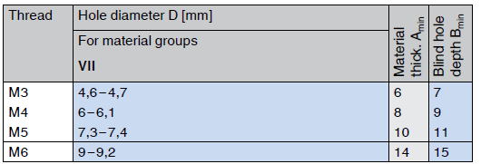
Recommended pilot hole diameters and material thickness / blind hole depths for threaded inserts Ensat®
Hard and brittle materials require a larger hole than soft and flexible ones. Whenever necessary, the most suitable hole diameter should be determined through application testing.
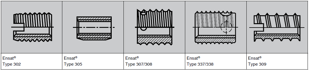
Ensat® Type 302
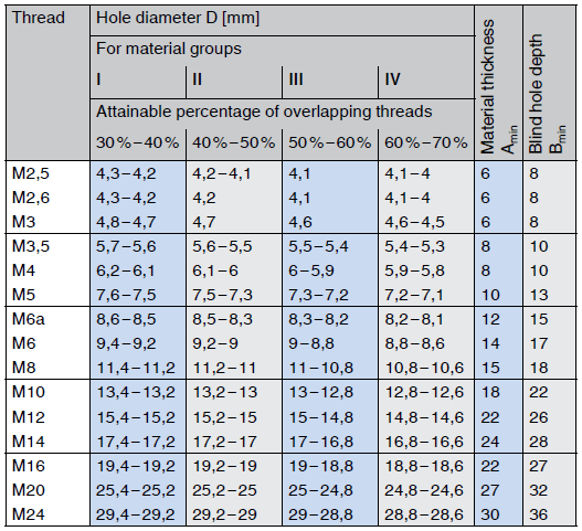
Ensat® Type 307/308/337/338
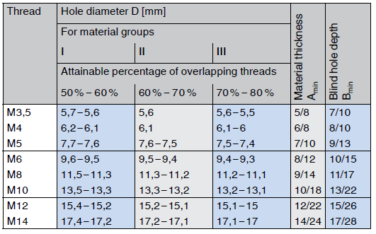
Ensat® Type 309
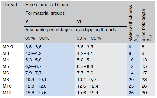
Ensat® Type 305
The pilot hole can be drilled or formed during die-casting
Countersinking the hole is usually not necessary; however it would facilitate installation and possibly prevent damage to the workpiece surface. It also would enable the insert to be flush with the work-piece.
Material thickness:
Length of Ensat® = shortest permissible material thickness A
Blind hole depth: Minimum depth B
Minimum wall thickness: The wall thickness is dependant upon
the hardness and / or strength of the workpiece material.
Recommendation for light metals: S ≥ 0,2 to ≥ 0,6 d2
Recommendation for cast iron: S ≥ 0,3 to ≥ 0,5 d2
d2 = Outside diameter [mm] of Ensat® insert
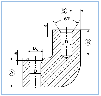
DA = + 0,2 to 0,4 mm
a = 1 to 1,5 x the pitch of the external thread